Choosing Brushless DC Motors is not simply a matter of selecting the highest speed or power rating. The right decision begins with the application’s real operating conditions. Consider continuous torque, peak torque, speed range, supply voltage, duty cycle, ambient temperature, and available installation space. A motor that looks impressive on paper may overheat inside a sealed enclosure. That detail matters.
Dr. Timothy J. Miller, a respected researcher in brushless motor technology, has emphasized, “The motor should be selected as part of the complete drive system.” This principle remains practical. The motor, controller, sensors, gearbox, and load must work together. A high-efficiency motor can still perform poorly when its controller cannot deliver sufficient current. An inexpensive design may also create unwanted vibration, audible noise, or unstable startup behavior.
Engineers should examine manufacturer datasheets carefully. Check torque-speed curves, winding resistance, rotor inertia, insulation ratings, and thermal limits. Then test the motor under realistic conditions. Measure temperature after extended operation, not only during a short demonstration. Small details reveal large problems. For example, a fan application may need quiet operation more than maximum torque. A robotic joint may value low inertia and precise feedback. A pump may require strong starting torque and reliable continuous service.
There is no perfect selection formula. Requirements often change during development. That is normal, but easy to overlook. This guide explains how to compare Brushless DC Motors systematically, avoid common sizing mistakes, and choose a solution that remains dependable beyond the laboratory.
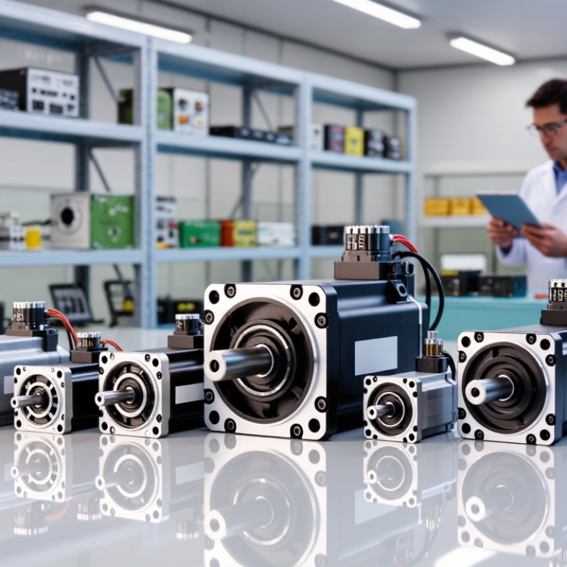
A brushless DC motor replaces mechanical brushes with electronic commutation. Its stationary stator contains copper windings arranged around a laminated iron core. The rotating section, or rotor, carries permanent magnets. When current enters selected stator windings, it creates a magnetic field. The rotor follows that field and produces torque.
The controller changes winding current as the rotor moves. Hall sensors or an encoder provide position feedback for accurate switching. Sensorless control estimates rotor position from back electromotive force. It can reduce wiring, but startup may hesitate under heavy loads. I have seen this during bench testing. The shaft moved unevenly before reaching stable speed.
Speed depends mainly on applied voltage and motor winding design. Torque depends strongly on current. A motor with a low winding resistance can deliver strong torque, but it may generate more heat. Check continuous torque, peak torque, thermal limits, and duty cycle together. Do not rely on rated power alone. Enclosure size, airflow, bearing loads, and controller settings can change real performance. A compact motor may look suitable on paper, yet overheat inside a sealed housing. That detail is easy to miss. A practical selection also considers feedback accuracy, starting load, noise, and required speed range. Reviewing measured temperature and current under realistic conditions often reveals weaknesses that specifications leave unclear.
A suitable brushless DC motor begins with a precise application profile. Record the supply voltage, continuous torque, peak torque, operating speed, and duty cycle. Include acceleration time and load inertia. These values often expose problems that a simple power calculation hides. A conveyor moving cartons may need steady torque, while a robotic joint demands rapid reversals and controlled holding force. Ambient temperature, dust, moisture, available space, noise limits, and expected service life also matter.
Examine the motor’s complete speed-torque curve, not only its advertised maximum speed. Continuous torque shows sustainable output, while peak torque describes short-term capability. Check winding resistance, torque constant, back-EMF, efficiency, and thermal resistance. A motor can meet the torque target but overheat inside a compact enclosure. Pay attention to rotor inertia and the feedback method. Hall sensors may suit basic positioning, while an encoder can improve low-speed control and repeatability.
Allow practical margin, but avoid excessive oversizing. A motor selected with little thermal headroom may fail during summer operation or repeated starts. I have seen projects rely on nominal voltage and overlook voltage drop in long cables. That mistake is easy to make. Test the motor with the real controller, coupling, load, and enclosure. Measure winding temperature, startup current, vibration, and speed stability. Datasheets may omit useful details, so request test conditions and tolerance values before approving the design.
Begin with the load, not the motor catalog. Measure the required torque, operating speed, acceleration, and duty cycle. A conveyor may need steady torque, while a fan usually demands higher speed and lighter starting torque. Measure the load.
An inrunner motor suits compact, high-speed systems with a separate transmission. An outrunner often provides stronger direct-drive torque at lower speeds. Check the torque-speed curve, not only the advertised peak value.
Continuous torque protects the motor during normal operation. Peak torque covers short acceleration events.
A useful calculation is power equals torque multiplied by angular speed. Include gearbox losses, bearing friction, and starting resistance. Small errors here can create large heat problems.
Heat matters. Compare the motor’s continuous rating with the real enclosure temperature, airflow, and mounting surface.
Select a controller that supports the required current, voltage, commutation method, and feedback signals. Hall sensors can improve low-speed control, while sensorless operation may struggle during startup.
Match motor inertia with the load inertia, especially in positioning equipment. Test the complete assembly under its actual cycle. A motor that performs well on a bench may overheat after repeated starts.
I have found that early estimates are often too optimistic. Recheck them with measured current, temperature, and acceleration. Oversizing can waste energy and reduce control response, so the “safer” choice is not always better.
How to Choose Brushless DC Motors for Your Application
Evaluating Controllers, Sensors, Efficiency, and Thermal Management
A brushless DC motor is only as effective as its control system. Start with the required speed range, torque profile, and supply voltage. A controller must handle starting current without overheating or triggering protection faults. It should also match the motor’s commutation method and operating feedback.
Hall sensors provide reliable rotor-position data at low speed and during startup. Sensorless control can reduce wiring, but it may struggle under heavy loads or sudden acceleration. For a conveyor that starts with a full package, that weakness matters. Check response time, current limits, braking behavior, and fault reporting before selecting a controller. Small details matter.
Efficiency changes across the operating map. A motor may appear efficient at its rated point but waste energy during frequent starts, low-speed operation, or partial loads. Review copper loss, iron loss, and controller switching loss together. Measure input power, output torque, and temperature during realistic duty cycles. A spreadsheet estimate helps, though it cannot replace testing.
Thermal management often decides service life. Keep winding temperature within the motor’s stated limit, then inspect the housing, mounting surface, and airflow path. Use thermal pads or a metal interface when heat must leave the case quickly. Dust can quietly reduce cooling performance. I have seen designs pass short tests and fail after hours of enclosed operation. That result deserves a second look. Allow margin for blocked vents, warmer ambient conditions, and imperfect assembly.
| Application Profile | Typical Continuous Power | Typical Speed Range | Recommended Controller | Sensor Configuration | Expected Motor Efficiency | Thermal Management | Key Selection Considerations |
|---|---|---|---|---|---|---|---|
| Small fans and blowers | 10–150 W | 1,000–5,000 rpm | Sensorless six-step or basic sinusoidal control | Sensorless back-EMF detection is usually sufficient | 70–85% | Natural convection; ventilation openings recommended | Prioritize low acoustic noise, reliable startup, compact size, and low standby power. |
| Pumps and laboratory equipment | 50–500 W | 500–4,000 rpm | Closed-loop speed control with current limiting | Hall sensors or encoder when precise flow control is required | 75–90% | Aluminum housing or fan-assisted cooling for continuous duty | Check pressure-torque requirements, fluid exposure, startup torque, and continuous operating time. |
| Robotic joints and positioning systems | 100 W–2 kW | 100–3,000 rpm | Field-oriented control with torque and position loops | Incremental or absolute encoder; Hall sensors may support commutation | 85–94% | Conductive path to the frame, thermal interface material, and winding temperature monitoring | Evaluate peak torque, backlash, feedback resolution, regenerative braking, and repeated acceleration cycles. |
| Conveyor and light industrial drives | 500 W–5 kW | 300–3,000 rpm | Closed-loop field-oriented controller with overload protection | Hall sensors for basic speed control; encoder for low-speed accuracy | 88–95% | Finned housing, forced-air cooling, or machine-frame heat sinking | Allow for starting torque, duty cycle, ambient temperature, shock loads, and service accessibility. |
| Battery-powered tools and mobile equipment | 250 W–3 kW | 1,000–20,000 rpm | High-frequency field-oriented control with battery current management | Hall sensors for robust startup; sensorless control for high-speed operation | 80–93% | Forced air through the motor and controller; temperature derating is important | Balance peak power, battery voltage, acoustic noise, weight, current limits, and intermittent duty. |
| Electric mobility and traction systems | 1–20 kW | 500–6,000 rpm | Automotive-grade field-oriented control with regenerative braking | High-resolution encoder or resolver; redundant position monitoring may be required | 90–96% | Liquid cooling or dedicated cold plate for sustained high load | Verify peak and continuous torque, operating voltage, vibration resistance, safety functions, and thermal derating. |
| Precision medical and laboratory motion | 50–750 W | 100–5,000 rpm | Low-ripple sinusoidal or field-oriented control | High-resolution encoder for accurate position and smooth low-speed motion | 80–92% | Low-temperature-rise design, conductive cooling, and validated insulation system | Emphasize low vibration, low cogging torque, position repeatability, cleanability, and fault detection. |
Comparing Installation, Maintenance, Reliability, and Total Cost
Choosing a brushless DC motor starts with the machine, not the catalog. Check load torque, speed range, duty cycle, ambient temperature, and available space. Installation details often decide performance. A motor that fits the shaft may still need a different controller, encoder, or cooling path. During commissioning, record current, vibration, and temperature at normal load. These readings create a useful baseline for future service.
Tips:
Ask for complete system data, including controller limits and cable length. Leave access around the motor for inspection and connector replacement. Specify sealed bearings only when contamination justifies them. Over-specification adds cost. Small details matter.
Maintenance is usually lighter because brushes are absent, but the motor is not maintenance-free. Inspect bearings, connectors, insulation, and cooling passages at planned intervals. Reliability depends on heat, electrical stress, alignment, and control quality. A clean installation can outperform a larger motor in harsh duty. Total cost includes controls, wiring, mounting changes, downtime, energy, and spare parts. I once underestimated downtime during a retrofit. The motor price was not the expensive part. Recheck assumptions with a small pilot test. Real machines are less predictable than spreadsheets.
Copper windings sit around a laminated stator core. Permanent magnets rotate on the rotor. Electronic switching creates changing magnetic fields. The rotor follows those fields and produces torque.
Hall sensors report rotor position during startup and low-speed operation. Sensorless control estimates position from back electromotive force. It reduces wiring. However, heavy loads can cause hesitant startup.
Measure the load’s torque, speed, acceleration, and duty cycle. Check the continuous torque rating, not only peak torque. Peak torque supports short acceleration events. Continuous torque protects normal operation.
An inrunner suits compact, high-speed systems using a separate transmission. An outrunner often provides stronger direct-drive torque at lower speeds. Review the full torque-speed curve. Advertised peak torque can mislead.
Heat may have nowhere to escape. Check ambient temperature, airflow, mounting surfaces, and enclosure size. A metal interface can improve heat transfer. Dust and blocked vents quietly reduce cooling.
Confirm voltage, current, commutation method, and feedback compatibility. The controller must handle starting current safely. Check current limits, braking behavior, response time, and fault reporting. Small details matter.
Not always. Gearbox losses, bearing friction, starting resistance, and controller losses affect results. Frequent starts may create more heat than steady operation. My early estimates were too optimistic.
Test the complete assembly under its real operating cycle. Measure current, temperature, acceleration, and output torque. Repeat the starts. A short bench test can miss hours of enclosed heating.
No. A larger motor may waste energy and reduce control response. Match motor inertia with load inertia, especially in positioning systems. Leave sensible thermal margin. The safer choice can perform poorly.
Choosing the right Brushless DC Motors begins with understanding how their rotor, stator, electronic commutation, and permanent magnets work together to produce controlled, efficient motion. The selection process should start by defining the application’s load profile, operating cycle, available power, required speed range, starting conditions, and environmental demands. These factors help determine the appropriate motor type, torque, power rating, and speed capability while ensuring the motor can handle acceleration, continuous operation, and occasional peak loads.
A complete evaluation should also include the controller, feedback sensors, efficiency, and thermal management requirements. Proper coordination between the motor and controller improves speed regulation, responsiveness, and energy use, while adequate cooling prevents performance loss and premature wear. Finally, compare mounting options, wiring, maintenance needs, expected reliability, serviceability, and total ownership cost. A motor with a suitable initial price may be less economical if installation is difficult, maintenance is frequent, or its efficiency and lifespan do not match the application.