0%

Choosing the right Worm Gear Motors begins with the machine, not the catalog page. A conveyor, packaging line, gate operator, and lifting platform demand different performance. Each application has its own load pattern, duty cycle, speed, mounting space, and safety expectations. A motor that works quietly for ten minutes may fail during continuous operation.

Mechanical design specialist Robert L. Norton offers a useful principle: “A gear train must be selected as part of the complete machine, not as an isolated component.” This idea matters when comparing Worm Gear Motors. Engineers should calculate output torque, starting torque, service factor, and required reduction ratio. They should also check thermal capacity, shaft loading, lubrication, noise, and installation position. Small details matter. A warm gearbox housing, repeated starts, or a misaligned coupling can reveal a poor selection.

Efficiency deserves honest attention. Worm drives can provide compact, high-ratio transmission and useful self-locking behavior. However, they may generate more sliding friction than helical or planetary designs. Self-locking is not guaranteed under every load, vibration level, or lubrication condition. That assumption can create risk. It should be verified.

A dependable selection process combines manufacturer data, field experience, and measured operating conditions. Record the real load, not only the rated load. Consider dust, moisture, ambient temperature, and maintenance access. Sometimes the smallest motor appears economical, but its limited thermal margin shortens service life. The better choice balances torque, efficiency, durability, control requirements, and total operating cost.
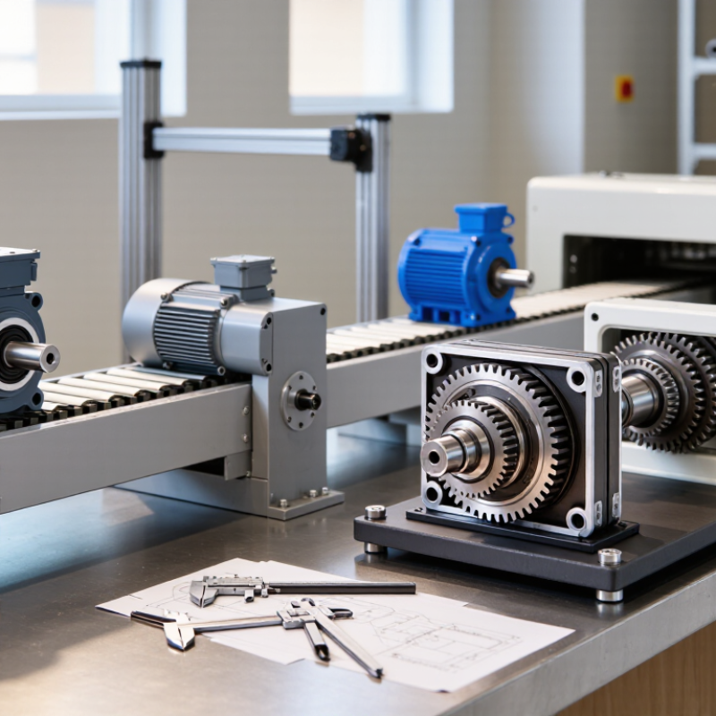
How to Choose the Right Worm Gear Motors?

What Is a Worm Gear Motor and How Does It Work?

A worm gear motor combines an electric motor with a worm gearbox. The motor spins a screw-like worm shaft. Its angled teeth engage with a circular worm wheel. This changes speed into stronger, slower rotation at a right angle.

The gearbox works through sliding contact, not simple rolling contact. That creates high reduction ratios in a compact housing. It also produces useful holding resistance when power stops. However, self-locking is not guaranteed in every design. Load angle, lubrication, vibration, and wear can change performance. I have seen poorly matched units overheat during repeated starts. The motor size alone did not explain the problem.

Tips: Check the required output torque, speed, duty cycle, and mounting position. Leave a safety margin, but avoid excessive oversizing. Excess capacity can increase cost and reduce efficiency. Confirm the gearbox ratio and output shaft direction. Ask for measured efficiency data, not only catalog estimates. A quiet test run is helpful, but it cannot replace temperature and load testing.

Worm gear motors suit conveyors, gates, lifts, and positioning equipment. Their smooth operation can reduce mechanical shock. Yet sliding gears usually generate more heat than many helical designs. Select suitable lubricant and provide ventilation when operating continuously. Installation alignment matters, too. Small errors can create noise, vibration, and premature wear. Recheck the choice after real operating trials, because laboratory conditions rarely match a dusty production area.

Which Performance Requirements Should You Define First?

How to Choose the Right Worm Gear Motors?

Before comparing worm gear motors, define the machine’s performance requirements. Start with the output torque needed during normal operation and startup. A conveyor moving full bins may need much more starting torque than its running torque suggests. Record the required output speed, too. Small speed errors can affect filling, indexing, or product spacing.

Duty cycle matters just as much. Will the motor run continuously, intermittently, or through frequent reversals? Estimate daily operating hours and the number of starts per hour. Then examine the load pattern. Shock loads, sudden stops, and inclined movement can quickly increase gearbox stress. I have seen projects fail because designers selected torque from ideal conditions only. That shortcut looked efficient, but it ignored real friction and peak loads. Allow a practical service margin, without making the motor unnecessarily large.

Tips: Measure the actual shaft load if possible. Check the ambient temperature, mounting position, noise limit, and available space. Confirm whether the motor can dissipate heat during slow, continuous operation. Worm gears may offer useful holding behavior, but do not assume they will replace a dedicated brake. Backlash also deserves attention when positioning accuracy matters. A simple test under the heaviest expected load often reveals more than a catalogue calculation. Record the results and question any estimate that feels too neat.

How to Choose the Right Worm Gear Motors? - Which Performance Requirements Should You Define First?

Performance Requirement What to Define First Useful Calculation or Selection Rule Typical Engineering Considerations Why It Matters for a Worm Gear Motor
Output Torque Required continuous torque, peak torque, and starting torque at the output shaft. For a rotating load: T = 9550 × P ÷ n, where T is torque in N·m, P is power in kW, and n is speed in r/min. Apply an appropriate service factor for shock and duty. Allow extra capacity for acceleration, friction, incline loads, jams, and intermittent overloads. Peak torque should not exceed the permissible gearbox or motor limit. Worm gearing can generate high reduction ratios, but friction and sliding contact reduce available output torque compared with an ideal calculation.
Output Speed Target operating speed, allowable speed range, and acceleration time. Approximate output speed: nout = nmotor ÷ i, where i is the gear ratio. Actual speed also depends on motor slip, load, and transmission efficiency. Check whether the application needs fixed speed, variable speed, or frequent speed changes. Confirm the permissible input speed of the gearbox. Higher reduction ratios generally provide lower output speed and higher torque, but may increase heat generation and reduce efficiency.
Gear Ratio Required ratio based on motor speed and the machine's operating speed. Select a ratio close to nmotor ÷ nrequired, then verify torque, efficiency, thermal capacity, and starting performance. Common worm reduction ratios range from approximately 5:1 to 100:1 in many standard applications, while the practical range depends on the gearbox design and load. A high ratio may help provide compact speed reduction, but it can also increase self-locking tendencies, heat, and power loss.
Duty Cycle Operating time per hour, starts per hour, load pattern, and whether the motor runs continuously or intermittently. Define the percentage of operating time and distinguish between continuous, cyclic, short-time, and reversing operation. Frequent starts, stops, reversals, and high inertia increase thermal and mechanical stress. Use the manufacturer's duty classification and thermal ratings. Worm gears produce sliding friction, so repeated or continuous operation can create more heat than similarly rated helical gearing.
Motor Power Mechanical output power required by the load, including acceleration and transmission losses. Estimate input power using Pin ≈ Pout ÷ η, where η is the total motor and gearbox efficiency. Do not select power from nominal load power alone. Consider startup current, voltage variation, ambient temperature, and service factor. The motor must provide enough power to overcome both the application load and the worm gear's transmission losses.
Efficiency and Energy Use Minimum acceptable efficiency, annual running hours, and energy-cost sensitivity. Compare total efficiency under the actual ratio, speed, load, lubricant, and temperature rather than relying only on a nominal value. Efficiency varies with ratio, speed, load, lubrication, and break-in condition. Lower ratios and favorable operating conditions are often more efficient than very high ratios. Sliding contact between the worm and wheel can result in substantial frictional loss, especially at high reduction ratios.
Starting and Breakaway Torque Maximum torque needed to start the machine from rest, including static friction and loaded conditions. Compare the motor's starting torque and gearbox peak torque rating with the required breakaway torque, not only the running torque. Conveyors, lifts, mixers, and machines with high inertia may require considerably more starting torque than their steady-state requirement. High internal friction can reduce starting efficiency and may cause a motor to stall if the selected capacity is marginal.
Backlash and Positioning Maximum allowable angular play, repeatability, and positioning accuracy. Specify backlash in angular units and evaluate it at the output shaft under the actual load direction and operating temperature. Standard worm gearboxes commonly have more backlash than precision planetary or certain helical solutions. Reversing applications require special attention. Backlash can affect indexing, registration, reversing accuracy, and the stability of closed-loop control.
Self-Locking and Backdriving Whether the load must remain stationary when power is removed and whether the output can drive the input backward. Treat self-locking as application-dependent. Verify the lead angle, efficiency, vibration, lubrication, wear, and load conditions through testing or engineering data. A worm gear should not be used as the sole safety device for suspended or hazardous loads; a brake or independent safety system may be required. Some worm arrangements resist backdriving, but self-locking is not guaranteed across all ratios, loads, speeds, and wear conditions.
Thermal Capacity Maximum ambient temperature, continuous running time, enclosure ventilation, and allowable gearbox temperature. Confirm that the actual input power, load, speed, and duty remain below the gearbox's thermal rating. High ambient temperature, poor airflow, frequent starts, and enclosed mounting can reduce allowable output torque and service life. Frictional losses are converted into heat, making thermal limits especially important for continuous operation and high ratios.
Radial and Axial Loads External loads on the output shaft, including belt tension, chain pull, gear force, and overhung load. Calculate shaft loads at the actual mounting distance and compare them with the gearbox's permissible radial and axial load ratings. Use external bearings when the machine load exceeds the gearbox shaft capacity. Check load direction and bearing life. Excessive overhung or thrust loads can damage bearings and seals even when the transmitted torque is within the nominal rating.
Environmental Protection Exposure to dust, water, chemicals, outdoor weather, washdown, humidity, and corrosive atmospheres. Specify the required enclosure protection level, corrosion resistance, cable entry, seals, and mounting orientation. Ingress protection is expressed by an IP code under IEC 60529. The required level depends on the actual installation environment and cleaning method. Water or contaminants entering the motor or gearbox can degrade insulation, lubricant, bearings, gears, and seals.
Electrical Supply and Control Voltage, phase, frequency, control method, starting method, braking, and speed control requirements. Match the motor rating to the available supply and verify compatibility with contactors, soft starters, variable-frequency drives, or servo controls. Check rated current, inrush current, insulation system, overload protection, electromagnetic compatibility, and required feedback devices. Incorrect electrical matching can cause overheating, nuisance trips, poor starting performance, or premature motor failure.
Mounting and Space Mounting orientation, available envelope, shaft arrangement, flange or foot mounting, and service access. Confirm dimensions, center distance, shaft diameter, keyway, bolt pattern, rotation direction, and lubrication suitability for the intended orientation. Restricted airflow and incorrect orientation may affect heat dissipation, oil distribution, sealing, and maintenance access. A mechanically compatible motor can still fail to perform if its mounting position or surrounding clearance is unsuitable.
Service Life and Maintenance Required operating life, inspection interval, lubricant type, seal replacement plan, and acceptable downtime. Evaluate bearing life, gear wear, lubricant condition, temperature, load spectrum, and maintenance accessibility. Correct lubrication, alignment, load selection, and periodic inspection are essential for maintaining rated performance. Worm and wheel sliding surfaces are sensitive to lubrication quality, contamination, temperature, and excessive loading.

How Do You Select the Correct Gear Ratio and Motor Power?

How to Choose the Right Worm Gear Motors?

How Do You Select the Correct Gear Ratio and Motor Power?

Select the gear ratio from the required output speed, not from motor size. If a 1,500 rpm motor must drive a shaft at 30 rpm, the nominal ratio is 50:1. Measure the load. Do not guess.

Calculate output torque before choosing motor power. For example, a 120 Nm load at 30 rpm needs about 0.38 kW at the gearbox output. If efficiency is 65% and the service factor is 1.25, the motor should provide roughly 0.73 kW. A 0.75 kW motor may fit, but starting torque, shock loading, and duty cycle can change the answer.

Worm gear efficiency varies with ratio, lubrication, speed, and temperature. A catalogue value is not a field measurement.

The International Energy Agency’s Energy Efficiency 2023 report states that electric motor systems consume about 53% of global electricity. Small sizing errors therefore affect both reliability and operating cost. The U.S. Department of Energy also identifies motor systems as major industrial energy users. In practice, I check thermal limits after calculating torque. A spreadsheet can still lie. Real conveyors pause, restart, and carry uneven loads. Revisit the selection using peak torque, daily operating hours, ambient temperature, and allowable backlash. The correct ratio may reduce speed perfectly, yet still produce an overheated gearbox.

Which Design Features Matter for Installation and Durability?

Choosing a worm gear motor starts with the installation environment, not the catalog ratio. IEA’s Energy Efficiency 2021 report estimates that electric motor systems consume nearly 50% of global electricity. Small efficiency losses can therefore become expensive over long operating hours. Check the required output torque, speed, duty cycle, and starting load. A high reduction ratio is not automatically better.

Mounting accuracy matters. Use a rigid base, verify shaft alignment, and avoid forcing the coupling into place. Even slight misalignment can increase bearing loads and heat. Select a housing with suitable ingress protection for dust, washdown, or outdoor exposure. Check the thermal rating too. Worm gears generate more sliding friction than many helical designs, so ventilation and lubricant quality directly affect service life. This detail is often underestimated.

Look for hardened gearing, adequately sized bearings, reliable shaft seals, and a clearly defined service factor. ISO 281 provides bearing-life methods based on load and speed, but real contamination can shorten calculated life sharply. The U.S. Department of Energy’s Motor Systems Market Assessment (2022) reports that motor systems represent about 70% of industrial electricity use in the United States. Efficiency deserves attention. Still, the most efficient unit may fail early if its seals, lubrication, or mounting do not match the site. That is the uncomfortable part. Assess noise, backlash, temperature rise, and access for inspection before approving the design.

How to Choose the Right Worm Gear Motors?

Which Design Features Matter for Installation and Durability?

Worm gear efficiency is strongly influenced by the number of worm starts and the resulting reduction ratio. Single-start designs generally provide high reduction in a compact package but generate more sliding friction and heat. Multi-start designs typically improve efficiency and thermal performance, while proper lubrication, correct mounting orientation, adequate thermal capacity, shaft alignment, and suitable ingress protection remain essential for long service life.

The values shown are typical engineering ranges for continuously lubricated worm gear systems; actual performance depends on load, speed, materials, lubrication, temperature, and operating conditions.

How Can You Compare Efficiency, Maintenance, and Total Cost?

How to Choose the Right Worm Gear Motors?

How Can You Compare Efficiency, Maintenance, and Total Cost?

Choosing a worm gear motor requires more than checking torque and purchase price. Compare its efficiency under your real operating load, not only the catalog rating. A motor running conveyors for ten hours daily may lose significant energy through heat and sliding friction. Measure input power, output speed, and delivered torque when possible. Small differences become expensive over several years.

Maintenance also deserves practical attention. Check whether the gearbox uses accessible lubrication points, durable seals, and clearly stated service intervals. Inspect oil condition, shaft play, unusual noise, and housing temperature during routine visits. In practical installations, overheating often reveals overload, poor alignment, or inadequate ventilation. Maintenance is not always predictable. Dust, frequent starts, and seasonal temperature changes can shorten service life.

Total cost includes energy, replacement parts, labor, downtime, and disposal. A cheaper unit may demand more frequent oil changes or create higher electricity bills. Conversely, a highly efficient model may not repay its price in a lightly used application. Build a simple five-year estimate using operating hours and local energy rates. Leave room for uncertainty. No spreadsheet predicts every failure, but it can expose weak assumptions before installation. Ask for test data, warranty terms, and realistic duty-cycle guidance from qualified suppliers.

FAQS

What should you define before choosing a worm gear motor?

Define output torque, startup torque, speed, duty cycle, and load pattern.

Why is starting torque important?

Starting a loaded conveyor may require far more torque than steady movement.

How does speed affect the selection?

Record the required output speed carefully.

Which duty-cycle details matter?

Note daily operating hours, starts per hour, reversals, and pauses.

How should shock loads influence the design?

Sudden stops, impacts, and inclined movement increase gearbox stress.

What installation details improve durability?

Use a rigid base and verify shaft alignment.

What environmental features should you check?

Match sealing and protection to dust, washdown, humidity, or outdoor exposure.

How do lubrication and gearing affect service life?

Worm gears create sliding friction, so lubricant quality and heat control matter.

Can a worm gear motor replace a dedicated brake?

Do not assume its holding behavior provides safe braking.

What final checks can reveal a poor selection?

Test the motor under the heaviest expected load and record temperature, noise, and backlash.

Conclusion

Worm Gear Motors combine a worm screw and a toothed wheel to transmit motion at a right angle while delivering high reduction ratios and useful torque. Their design can also provide natural resistance to reverse motion, making them suitable for applications that require controlled movement and stable positioning. Before selecting a model, define the required speed, output torque, duty cycle, load characteristics, operating environment, and available power supply.

Choosing the correct gear ratio and motor power helps prevent overheating, excessive wear, and poor performance. Installation space, shaft arrangement, mounting method, enclosure protection, materials, and thermal management should also match the working conditions. When comparing Worm Gear Motors, consider efficiency alongside purchase price, lubrication needs, service life, noise, and ease of maintenance. A slightly higher initial investment may offer better reliability and lower total operating costs over time.

Ethan

Ethan

Ethan is a professional marketing specialist and trusted content contributor with a deep understanding of the company’s products, services, and customer needs. With a strong combination of market insight, product knowledge, and clear communication skills, he helps readers make informed decisions......