What Are Coreless DC Motors and How Do They Work?
Coreless DC Motors are compact electric machines built without the traditional iron core inside their rotating armature. Instead, the winding forms a lightweight cylindrical basket. This structure changes how the motor starts, accelerates, and responds to control signals.
Dr. Fritz Faulhaber, whose 1958 design helped establish modern coreless motor technology, described the principle clearly: “A lightweight rotor delivers fast response and high efficiency.” His statement captures the main engineering advantage, although it does not explain every design trade-off.
When current enters the winding, it interacts with the permanent magnets surrounding it. That electromagnetic force produces torque and turns the rotor. A commutator and brushes switch the current as the rotor moves. Some newer designs use electronic commutation instead.
The missing iron core matters. The rotor has lower inertia, so it can reach speed quickly. It also avoids much of the iron-related eddy-current loss found in conventional motors. The result can be smooth motion, low electrical noise, and precise positioning.
Small details become important here. A camera lens may require a gentle, rapid adjustment. A surgical pump may need stable rotation at low speed. A robotic joint may demand repeated starts without hesitation.
However, coreless construction is not automatically superior. The winding can struggle with heat removal, especially during continuous operation. Brush wear can also limit service life. These limitations are easy to overlook.
The phrase “high efficiency” needs context. Efficiency depends on load, speed, voltage, cooling, and controller quality. Engineers should test the complete drive system, not judge the motor alone.
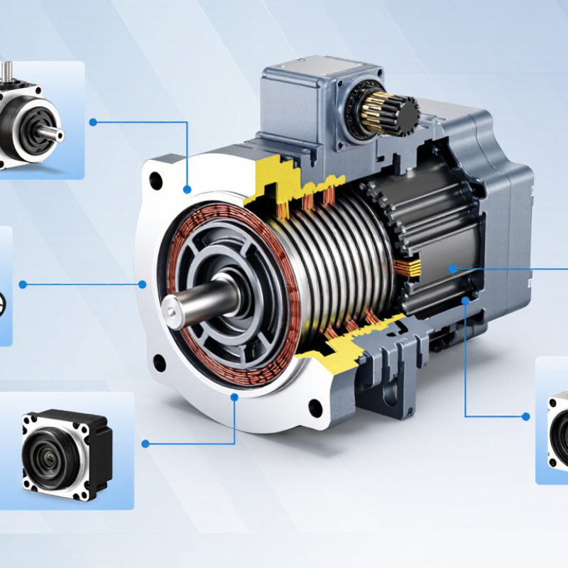
Coreless DC Motor: Definition and Distinctive Design
What Are Coreless DC Motors and How Do They Work?
A coreless DC motor uses a hollow, iron-free rotor instead of a conventional iron armature. Its winding forms a thin cup around the stationary magnet assembly. This distinctive design removes much of the rotor’s magnetic mass. The rotor can accelerate quickly, stop sharply, and respond to small voltage changes. The rotor is light.
In a brushed version, current enters through brushes and a commutator. The energized winding creates a magnetic field that interacts with the permanent magnets. This interaction produces torque and turns the cup-shaped rotor. As the commutator switches electrical paths, the magnetic pull continues around the rotor. During bench testing, this fast response is noticeable in compact positioning equipment and small pumps. There is less stored rotational energy to overcome.
The design also introduces practical limits. Without an iron core, magnetic flux is less concentrated, so continuous torque may be lower than expected. Heat leaves the thin winding through limited surface paths. That can restrict sustained loads. The term sounds absolute, but it is not: some assemblies include magnetic or structural materials around the winding. A coreless motor is not automatically better. Engineers must check voltage, current, temperature rise, brush wear, and required acceleration. In real applications, a slightly larger motor may perform more reliably than a smaller, faster choice. This trade-off deserves careful measurement, not assumption.
What Are Coreless DC Motors and How Do They Work? — Coreless DC Motor: Definition and Distinctive Design
A coreless DC motor is a permanent-magnet brushed motor whose rotor winding forms a lightweight self-supporting cylinder instead of being wound around a conventional iron core.
| Design or Performance Dimension | Coreless DC Motor Characteristics | Engineering Significance |
|---|---|---|
| Basic Definition | A brushed direct-current motor with a hollow, ironless rotor winding and a permanent-magnet stator. | The absence of a laminated iron rotor reduces rotating mass and eliminates most rotor iron losses. |
| Rotor Construction | The armature winding is formed as a cylindrical or basket-like coil that rotates around a stationary magnet assembly. | The winding can accelerate and decelerate quickly because it has low inertia. |
| Magnetic Circuit | The permanent magnets and magnetic return path are generally located inside or around the hollow rotor. | Magnetic flux crosses the air gap directly through the energized winding without passing through a conventional iron armature core. |
| Operating Principle | When DC current flows through the rotor conductors, the interaction between current and the stator magnetic field produces electromagnetic torque. | Mechanical commutation switches current between winding sections so that torque remains available as the rotor turns. |
| Commutation Method | Usually a mechanical commutator and carbon or precious-metal brushes are used. | This provides simple electronic control but introduces brush wear, electrical noise, and a finite service life. |
| Typical Supply Voltage | Common designs are available for low-voltage systems, frequently from approximately 3 V to 24 V DC. | The appropriate voltage depends on winding resistance, required speed, thermal limits, and the application duty cycle. |
| Speed Capability | Many small coreless motors operate from several thousand revolutions per minute to above 20,000 revolutions per minute when properly rated. | High speed is enabled by low rotor inertia, but bearing limits, commutation, balance, and heat dissipation must be considered. |
| Torque Capability | They typically provide low to moderate continuous torque and can deliver short-duration peak torque. | For high-load applications, a gearbox or a larger motor may be required because the rotor has limited thermal mass. |
| Torque Response | Torque responds rapidly to changes in current, with very little mechanical delay. | This makes the motor suitable for precision positioning, rapid actuation, and dynamic closed-loop control. |
| Rotor Inertia | Substantially lower than that of a comparable iron-core armature; the exact value depends on motor size and winding geometry. | Low inertia improves acceleration, braking, reversing, and servo response. |
| Cogging Torque | Very low or nearly absent because the rotor does not contain conventional iron teeth that strongly interact with the stator field. | Low cogging helps produce smoother low-speed motion and improves positioning behavior. |
| Iron Losses | Rotor hysteresis and eddy-current losses are greatly reduced because the rotor has no conventional ferromagnetic core. | Efficiency can remain favorable at high speed, although copper, brush, bearing, and windage losses still occur. |
| Thermal Behavior | The winding is located on the rotating structure and may have limited direct access to the motor housing for heat transfer. | Continuous output is often limited by winding temperature rather than by short-term electromagnetic capability. |
| Electrical Time Constant | Often low because the winding inductance is relatively small compared with that of an iron-core armature. | Low inductance enables fast current changes but may require a suitable current-controlled driver to limit electrical transients. |
| Starting Behavior | Provides useful starting torque without the strong preferred rotor positions associated with many iron-tooth designs. | Starting can be smooth, particularly in applications requiring low-speed movement and frequent starts. |
| Noise and Vibration | Low cogging reduces torque ripple, but brush contact can generate audible noise, electromagnetic interference, and mechanical wear. | Filtering, suppression components, shielding, and appropriate brush selection may be needed in sensitive equipment. |
| Control Requirements | Speed is commonly controlled by adjusting average voltage with pulse-width modulation or by regulating current. | Feedback from an encoder, tachometer, or Hall sensor can improve speed and position accuracy. |
| Efficiency Considerations | Efficiency varies with load, speed, winding design, brush type, and operating temperature; it is not automatically higher in every application. | Motor selection should use the manufacturer’s efficiency and thermal curves at the actual operating point. |
| Service Life | Service life is commonly governed by brush and commutator wear, bearing wear, operating speed, current density, and environmental conditions. | Coreless construction reduces rotor losses but does not remove the maintenance limitations of a brushed commutation system. |
| Typical Applications | Compact actuators, portable instruments, miniature pumps, camera mechanisms, medical devices, robotic joints, and precision positioning systems. | These applications benefit from compact size, rapid response, low cogging, and controllable low-speed operation. |
| Key Advantages | Low rotor inertia, fast dynamic response, low cogging torque, reduced rotor iron losses, compact design, and smooth operation. | The design is especially valuable where rapid movement, precise control, and low mechanical disturbance are more important than very high continuous torque. |
| Key Limitations | Limited continuous thermal capacity, brush wear, electrical noise, lower overload tolerance in some designs, and potentially higher manufacturing complexity. | Careful sizing is necessary to prevent winding overheating, excessive commutator wear, and operation outside the rated speed range. |
Note: Performance ranges shown above are general engineering characteristics rather than specifications for a particular motor. Actual voltage, speed, torque, efficiency, temperature rise, and service life depend on the motor’s dimensions, winding, magnets, bearings, commutation system, and operating conditions.
FAQS
Direct current enters a lightweight copper winding inside a permanent magnetic field. The interacting magnetic fields create torque and turn the shaft.
The rotor has no iron core. Its winding forms a light, rotating coil, which reduces inertia and supports faster movement.
The lightweight rotor stores less rotational energy. It can change speed and direction with less delay.Very responsive.
They switch the winding’s current direction as the rotor turns. This keeps the torque pointed forward instead of stopping the motion.
The winding has limited thermal mass, so heat can build quickly during continuous operation. Sealed housings may make cooling even harder.Heat builds quickly.
They suit compact medical instruments, camera focusing systems, laboratory pumps, precision valves, and small robotic mechanisms.
Check voltage, continuous torque, peak torque, speed range, space, and thermal limits. Also examine shaft loading, gear backlash, noise, and feedback requirements.
A motor may spin quickly without load but overheat during real movement. Duty cycle, acceleration current, and stall conditions reveal more useful performance.A test fixture can mislead.
No. Efficiency depends on load, voltage, friction, temperature, and operating time. Their low inertia can reduce energy waste, but poor cooling may offset that benefit.
Measure current during acceleration, starts, stops, and direction changes. Rated current alone may hide short, demanding power bursts.
Test the motor under its intended load and duty cycle. Allow reasonable design margin, but excessive margin can add unnecessary size and cost.Testing still matters.
Conclusion
Coreless DC Motors are compact electric motors designed without the traditional iron core in the rotor. Instead, their lightweight winding forms a self-supporting cylindrical structure that rotates around permanent magnets. This distinctive design reduces rotor inertia and eliminates many core-related losses, allowing the motor to respond quickly and operate smoothly. Key components typically include the rotor winding, permanent magnets, commutator, brushes, shaft, bearings, and housing. When electrical current flows through the winding, it creates a magnetic field that interacts with the permanent magnets, producing torque and continuous rotary motion as the commutator switches the current direction.
The main advantages of coreless motor technology include fast acceleration, precise control, low vibration, quiet operation, and high efficiency in short-duration or dynamic applications. However, these motors may have limited heat dissipation, reduced overload tolerance, and brush wear in some designs. They are commonly used in compact mechanisms, portable equipment, medical instruments, optical systems, and small robotic devices. When selecting one, users should consider voltage, speed, torque, duty cycle, efficiency, size, thermal conditions, control requirements, and expected service life.
